[slickr-flickr tag=”tc18v3″ type=”galleria”]

This is the home page for my VFD tube clock project, the TC18.
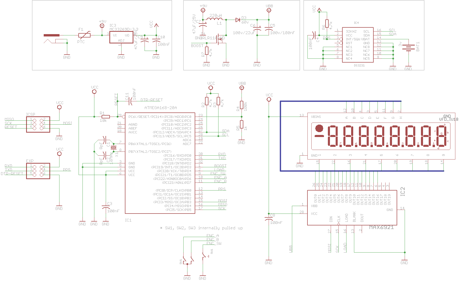
The TC18 is a clock built around an old Russian IV-18 VFD tube. You can read the story of how it came to be at this blog post.
Purchase Info
I have a single clock for sale on eBay! This is the only one I will be selling, so please bid on the auction!
Specifications
- IV-18 Russian VFD (Vacuum Fluorescent Display) tube for display.
- ATmega328P microcontroller running at 16MHz.
- Running Arduino bootloader for easy update.
- Completely custom firmware.
- DS3231 RTC (Real Time Clock) chip for keeping extremely accurate time.
- Lithium battery for keeping time during main power loss.
- MAX6921 VFD driver for controlling the 17 high voltage outputs.
- Custom high voltage boost switching power supply with voltage feedback; controlled by CPU.
- EEPROM storage of all configuration parameters.
- Rotary encoder with push to select for configuration menus.
- Custom aluminum enclosure designed by John Pfeiffer and realized by myself.
Downloads
Credits
The enclosure of this clock was designed by John Pfeiffer at http://blog.giantpachinkomachineofdoom.com/
Parts of the circuit are based on Ladyada’s Ice Tube clock at Ice Tube Clock
That clock is sold in kit form by Adafruit at Ice Tube Clock Kit
Some of the parts used in the schematic and board drawings are from the Sparkfun Eagle library at SFE_Footprint_Library_Eagle
Videos
Press and Exposure
License

This work is licensed under a Creative Commons Attribution-Share Alike 3.0 United States License.
Your project amazed me. Something I have wanted to do all my life (62yrs). I am a electronic engineer of the old school and fascinated with the amount of labor of love you put into this. If you start a company, you will be a millionaire soon. Good luck and will look for you on Facebook.
I love the design. I have been thinking of making one myself, and I like how you used an external RTC in the circuit. I was wondering if you could throw a schematic up in pdf format, as I am using a different design program, and can’t import eagle files.
Hi there,
I’m interested in building a VFD lamp but i have a problem with MAX6921 i live in Poland the chip isn’t available in my country, did You buy the chip form Maxim od they send You a sample? I wanted 3 samples (need to make 3 clocks) but Maxim don’t seend them to my country eather. Have You got any ideas?
With Regards
Shalvan
Shalvan,
I got 2 chips as samples from Maxim and then I ordered 5 more directly
from them. You can buy directly from Maxim at http://www.maxim-ic.com and I
believe they will ship worldwide.
Ray, I put up a PNG of the schematic in the download section.
Hi there,
I am definitely interested in buying one of those clocks if you ever happen to offer some. Please let me know if that happens. Awesome work!
Cheers,
Andi
Very nice!!! just one question, is the free end of the tube supported at all? hard to tell in the pictures.
again great job!!
Mark
could you put a version of the script that only handles time and vfd update (so no rtc or boost circut)?
@peter – the code is really well documented. It should be easy enough for you to rip out the bits you don’t need. Feel free to email me at jason@vonnieda.org if you have any specific questions.
@jason (nice name does remind me of something else)
what are the pinout of the MAX6921AQI+ socket (it is the square chip)
i have searched but nobody can tell me
and i saw you used one bevore sooooo
(it has word the code is a go witout the boost and eeprom)
@peter
The pinout is on page 11 of the datasheet at: http://datasheets.maxim-ic.com/en/ds/MAX6921-MAX6931.pdf
@jason that is not what i mean
i said socket
but it can happen
i need the pinout of the plcc socket 😛
@peter
There are different PLCC-28 sockets available and some have different pinouts. SMD vs. PTH, for instance. In any case, the data sheet for the socket you are using should show the pinout.
The one I used was PTH and the data sheet has the pinout at:
http://www.usa-assmann.com/specs/a-ccsxx-x-r.pdf
Jason,
Are you making a kit for this? I would love to have one and it looks like it would be a blast to assemble and program!
Jason
Hello Jason
That is one awesome looking clock.
I have ordered and built the Ice Tube Clock from Adafruit, but I really like yours.
You have many more features on yours, and you have the supercool Casing feature going for yours as a bonus.
I don’t do programing, so I would have problems adding the features to mine.
It would be really great if you decided to make a kit for your clock available.
Kevin
Hi Jason and Kevin, I would love to make a kit but I have not found a way to do it cost effectively. Many of the parts require extensive hand labor and lots of machine time on my little CNC mill. I am still trying to find ways to develop a kit, but nothing is going to happen soon I’m afraid.
Jason,
I tried to get a company to machine the parts for me,using the PXD files in the zip folder, but the said that there were no dimensions to work with. They said they needed “thickness, width, length, holes sizes, etc…” If you could help me out that would be great. Thanks
I want to add alarm to this clock,can someone help with programing please
Hi Jason,
I would very much want to get hold of a kit for this clock….this is awesome. It would be a shame not to have this mass produced!!!
This a great work of art! Very stylist.
Roland
Hi jason,
i’m still working on your clock, to build my own version. First of all i re-designed it, to be done with Throught Hole component exeption for VFD controller and RTC.
Second, i need Umidity, so I added a DHT11 sensor instead RTC temp misuration. I’m also modifing software and your program is very amazing and some time not understandable for me. I’m working with Arduino from 2 month, but I became from PIC’s Basic programmer.
Another functionality I’d like to add, is a light sensor, a photoresistor, to add a AutoBrigthness functionality. I tried to add sensor to AnalogPin3 and use Arduino Analogic utility but it does not work, display became crazy. As I can understand from your code, you use ADC in some “RAW” mode and is not possible to use it in arduino.
Can you helpme with your code, to add this?
My first idea is to remove voltage control interrupt function and handle is in main loop togheter with Brightness control, but i’m not sure.
Can you help me?
Thanks
Marco
I am in the proses of making one would u be able to help me with the circuit bord. This is what has captured my atention into this hobby have never done any thing like this and I would love your help.
Very cood build and beautiful PCB-layout! – I can see that you did away with the AC-drive on the Filament, with the small Brightness-gradient visible. It’s not THAT visible on the video, how about in real life ? The tests i’ve done with my IV18 tubes shows quite substantial gradient across the tube. Have you tried adding an auxillary winding on the inductor, with a grounded center-tap. This way you can power the filament with AC and avoid the gradient.
Wonderful work!
I found the output connector on theschematic with PPS leg exposed. Is this an input for 1PPS external signal?
Is the firmware source available for download?
When I try to compile and verify, it shows an error, what is the reason, I am using Arduino V1.85
Thank you!
Brick Ling